Production years:
- 1964 – 1967 blackface circuits AA964, AA864, AB568
- 1967 – 1978 silverface circuits AB568, AA270
- 1978 – 1982 silverface circuits with push/pull volume boost
Tube layout
Blackface model tube layout (Seen from behind, V1 is to the right side)
- V1 12ax7 = Preamp normal channel
- V2 12ax7 = Preamp vibrato channel
- V3 12at7 = Reverb send
- V4 12ax7 = 1/2 Reverb recovery and 1/2 gain stage for vibrato channel
- V5 12ax7 = Vibrato
- V6 12at7 = Phase inverter
- V7 6L6 = Power tube #1
- V8 6L6 = Power tube #2
- V9 GZ34 = Rectifier tube
Summary
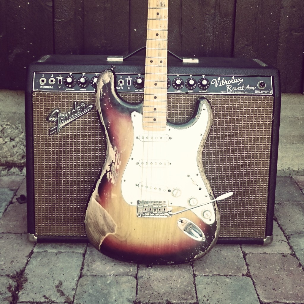
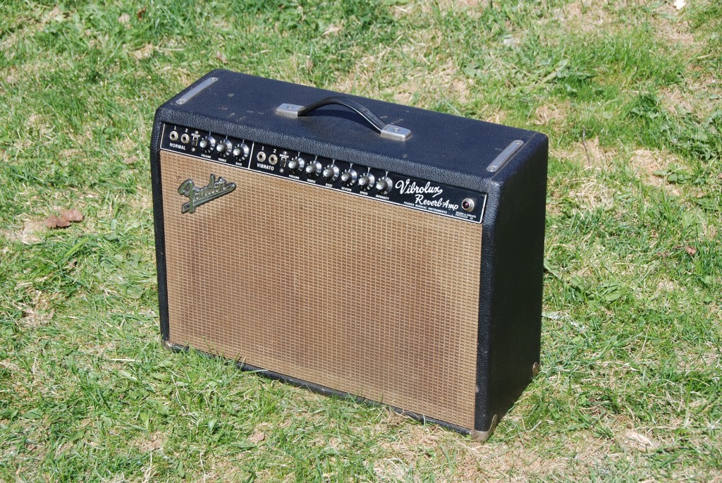
The 35w blackface Vibrolux Reverb (VR) is the smallest member of the blackface/silverface 6L6 Fender amp family. Its strength lies in the sweetness and early breakup caused by the smaller transformers than the Super Reverb, Vibroverb and Pro Reverb. The Vibrolux is quite similar to the Pro Reverb 2×12″ except for the smaller speakers, output transformer and power transformer. Hence, less clean headroom. 10″s provide a more scooped, responsive, punchy and sparkling sound than 12 inch speakers. The 12″s are fuller, warmer, looser in the low end while having more mids and a more three-dimensional tonal spread. Like all silverface amps, the Vibrolux Reverb was modified in the CBS periods to increase the clean headroom.
The Vibrolux Reverb has become a very popular amp. A stock VR offers a wide range of tonal possibilities and can be both big and small with just a few minor tricks. Out of the box the silverface and blackface amps will fit many occasions and are therefore not widely discussed in terms of serious mods like, for instance, the Princeton Reverb. Still, they are vintage amps requiring service and maintenance. Speakers, tubes and caps needs to be replaced and these will affect the tone a lot. In addition to that we’ll present some other tricks how to make it smaller, bigger, cleaner, darker, brighter, firmer or looser.
We would like to talk about one very cool BF Vibrolux we came over in 2010. It was loaded with one Weber 10A150 and one Jensen C10q delivering together a decent, loud clean sound and with firm lows. You can hear the sparkling tones coming from the Jensen C10q supported by the strong lower mids from the Weber. There was plenty of clean headroom with the stock “AB763” tube configuration (12AT7 phase inverter and GZ34 rectifier) for funky chords and stingin’ clean notes at volume between 3 and 4. If we wanted to get more breakup from the amp for some raw blues tones and keep he same volume, we did the following:
- Disengage the Jensen speaker and use only the weber 10A150. Running the amp at 8 ohms instead of 4 pushes the power tubes harder and lowers the clean headroom. Since one speaker offers less volume than two speakers we need to turn the volume knob up to stay equally loud as before. We have pushed the amp beyond its sweet spot. We must also increase the treble due to the Weber’s dark tone. This speaker just loves fat, distorted tones.
- Replace the GZ34 with a 5U4GB to lower the amp’s headroom even more and get more sag and compression. We don’t adjust bias if it is only a temporary switch of rectifier tube. If we had 35-37mA bias current with the GZ34, we would probably get around 30mA with a 5U4GB, which is a bit low but fair enough.
- Pull the V1 12AX7 tube to get more preamp gain and a thicker sound. We always use the vibrato channel.
- Use the 12AX7 from V1 as phase inverter tube V6. This reduces the clean headroom significantly.
Playing the amp around volume 5 and 6 gives a raw, unfiltered texas blues tone out of the single 10″ Weber 10A150.
Here is a video that gradually demonstrates the effects of some of the mods and tricks described here. To see embedded text comments, go to video on Youtube.
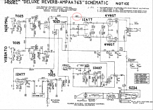
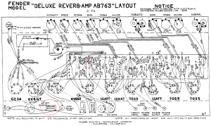
You’ll need schematics to implement some of these mods. http://www.ampwares.com/fender.asp. We usually start with explaining a mod from a functional perspective where we relate to components in the logical schematics diagram. Finally we point out location of components in the physical layout diagram.
Speakers The blackface and silverface Vibrolux came with several different production speakers; Blackface amps had Jensen C10q (1,25″), C10ns (1,5″) or Oxford 10L5 while the silverfaces could have Oxford 10L5 or CTS ceramic. Having played all of these speakers our favorites are, not surprisingly, the Jensen and CTS speakers. A blackface Vibrolux with a pair of gold and red labeled Jensen is just a fantastic amp. The Jensen serial number starts with 220 followed by production year X(X) and week nr YY. 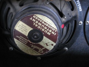 We have had a silverface Vibrolux in our gear basement with a set of blue labeled “Fender” CTS speakers (serial number 137-XXYY). This amp performed extremely well too, with lots of punch and sparkle. From a player’s perspective, you’ll get more value for the buck with a CTS silverface amp than with a blackface. Swapping speakers is the easiest and most effectful change you possibly can do to your amp. The 2×10″ speaker configuration with open back cabinet is convenient, efficient and powerful “enough” for us. Sonically, it offers everything we look for in a Fender amp; A dynamic and sensitive touch, brightness, volume, ambience, spread and a decent weight. The amp is not very heavy compared to the 2×12″ or 4×10″ amps. We are therefore not that afraid of installing heavy speakers in the VR if we want big magnets with lots of power.
See page How to select speakers for general speaker recommendations. See also the Super Reverb page for combinations of different speakers.
Custom baffle with 10″ + 12″ speakers.
If you want to get a bigger and warmer tone from your Vibrolux you may replace the original baffle with one that fits a 12″ and 10″ speaker. The 12″ speaker goes to the right side, amp seen from behind, opposite of the power transformer which blocks the opportunity of a 12″ speaker on the left side. We once acquired one rough looking 66 Vibrolux Reverb with an unoriginal baffle with unoriginal 10″ speakers. We cut a new baffle and mounted 2×4 speaker screws for the 12″ and 10″ speakers. The speakers we chose were Weber 12F150 12″ and a Jensen Jet series Tornado 10″. This particular Jensen speaker with a NeoDymium magnet will hold up against almost any 12″ speaker and is very efficient, responsive, punchy and and can take a lot of beating without farting out or breaking up. Where the Jensen NEO-100 can be a bit dull and muddy, the Jet series Tornado excels with quacky and bell-like sparkling blackface tones. The Weber is a bit darker and is responsible for the mids and lows. If you have a rough player’s amp where you don’t care about originality, this is a highly recommended mod.
12AY7 or 12AT7 as preamp tubes – Less preamp gain.
If you want cleaner and spankier preamp distortion characteristics, you may replace the V1 or V2 12AX7 preamp tube with 12AT7 and 12AY7. These tubes have different frequency responses than 12AX7, particularly when distorting. People describe these tubes to have less harsh and buzzy distortion. This mod does not alter the tone significantly when amp is played clean or when only the power amp section distorts. You’ll have to increase the volume setting to achieve a similar volume as before. The reason is that 12AX7 tube has a voltage gain factor = 100, while 12AT7 = 60 and 12AY7 = 45.
Pull out the V1 normal channel preamp tube – More preamp gain in vibrato channel
We’ll start with saying that this is a mod we personally do to all dual channel blackface, silverface and reissue amps. It is so easy to enable and disable that it can hardly be called a mod. If you are like most players and only use the Vibrato channel (reverb, tremolo, the bright cap and the extra gain stage), you should pull out the V1 tube. This is the preamp tube for the normal channel which you are not using when playing the Vibrato channel. Vice versa; If you’re using the Normal channel, you can pull out the V2 tube. All AB763-similar circuits (Deluxe Reverb, Super Reverb, Pro Reverb, Twin Reverb, Vibroverb, Vibrolux) are designed so that they share the cathode cap and resistor (25 uF/1500 ohm) and pulling one of the tubes will changes the effective value of the resistor they both share. If you pull one tube the other channel’s tube will be hotter biased and offers more gain. The amp will play louder than before given the same volume knob setting. The stronger signal will push the second gain stage (V4 tube) harder and give you increased sustain, compression and harmonics. This mod does not change the amp’s clean headroom but increases the preamp gain and preamp distortion.
This mod is one of Cesar Diaz’ tricks in the Fender Custom Shop Vibroverb 64 which he always did to Stevie’s amps. This mod is safe. It has stood the test of time and been been done by players in 50 years in blackface Fender amps.
Replace the 12AT7 PI tube with a 12AX7 or 12AU7 – Less clean headroom.
Very practical mod at practice and low volume environments. This mod reduces the amp’s clean headroom and you’ll achieve sweet spot at a lower volume. You’ll notice that the amp gets looser and with less attack. Tips: If you pulled the V1 12AX7 tube you may use it as V6 phase inverter.
12AX7 as phase inverter tube will give the most effect out of this mod. 12AU7 will be in between 12AT7 and 12AU7.
Replace the 12AT7 reverb driver with 12AU7 – Better reverb control.
Reverb is an important character with vintage amps, yet so individual and mysterious. We all know that speakers change their tonal character during age. So does the reverb. The reverb function sounds and behaves differently between “identical” vintage amps. Some amps have long, lush and soft reverb while others are mushy and overwhelming. We often find the reverb sweet spot around 2.5 on the reverb pot, varying from 2 to 4. Some amps are sensitive and difficult to control the reverb on. The whole dynamic area can be within a narrow interval, i.e. 2 and 2.5. These amps require a careful touch when dialling in the reverb, which irritates us.
The reverb circuitry consists of two tube sections (reverb driver V3 and reverb recovery V4) and the physical reverb tank. All these components will drift during age and minor differences in component values are noticeable to man’s ear.
If you replace the V3 12AT7 reverb driver with a 12AU7, you will reduce the effect of the reverb and it will be much easier to control with the reverb knob. So simple as that.
Use normal channel for reverb control – Adjust EQ and depth of reverb.
This mod is relevant only for two-channel amps with normal and vibrato channel. This trick is great for the reverb enthusiasts among us, and who is not? Plug your guitar into the vibrato channel, then unplug the reverb return cable on the back of the amp (the one that comes from the reverb tank output) and plug it into the normal channel input. You will need a converter to go from male phono/RCA jack to a 1/4″ male jack. You may now use the normal channel as a reverb control where you can adjust the depth and tone using the volume, bright switch, treble and bass knobs (and mid if you have a Twin Reverb). The reverb knob on the vibrato channel will have no effect any longer.
This mod is not applicable together with the Pull V1 mod, as you need the normal channel preamp tube.
Diode rectifier – More clean headroom.
This mod is for those who need more power, clean headroom and attack. It is very practical to carry with you those small Sovtek plastic adapters that quickly and easily replaces the rectifier tube. You’ll increase the power of the amp with a few watts. The diode rectifier will feed your amp’s filter caps with a higher and “faster” DC voltage compared to a tube rectifier. The fact that it delivers a slightly higher DC voltage to your power tubes (via the filter caps) means an increase of the tube voltage gain factor. When you hit a hard chord the preamp and power tubes will require energy and current is flowing from the DC filter caps which are charged up by the rectifier. If the rectifier can deliver more energy more quickly, you’ll have more power and attack. Check also out Ted Weber’s “Copper Cap Rectifiers” that emulates the sag of a tube rectifier.
Tremolo disconnect mod – More preamp gain in vibrato channel.
The effect of this mod is similar to pulling the V1 normal channel preamp tube when playing the vibrato channel. This is also a very popular mod in AB763-similar circuits (Super, Twin, Vibroverb, Pro Reverb, Deluxe, Vibrolux).
By original design the tremolo circuit will absorb current/signal even when one turns the tremolo off with the footswitch. This mod suggests to entirely disconnect the tremolo circuit from the signal path by replacing the tremolo intensity pot with a switchable pot (spst). One side effect with this mod is a noticeable click and a volume difference between tremolo on and off using the new spst pot. If one uses the tremolo regularly one should still use the tremolo pedal to enable/disable the tremolo and leave the intensity spst pot at your desired level. The spst pot is not good for enabling and disabling the tremolo very often (because of the click and the volume difference) but is a nice when you play without tremolo. A good thing with this mod is that you have both the tremolo pedal and spst pot to use.
With a new switchable/spst pot set at intensity=0 the mod will kick in and raise the signal level in the preamp section, right before the phase inverter. Once you’re turning up the tremolo the circuit is connected again and the tone will remain original. This mod does not increase the amp’s clean headroom. We would describe the effect as making the tone richer, fuller and more powerful with stronger mids that pushes the power amp section harder (phase inverter + power tubes). We like this mod a lot for stratocasters wi the Fender AB763-similar circuits since they boost a relatively scooped and thin sounding guitar and amp. In addition to pulling the V1 tube, this mod is one of those must have mods which we never undo once having implemented it.
This mod is one of Cesar Diaz’ tricks in the Fender Custom Shop Vibroverb 64 which he always did to Stevie’s amps. This mod can be implemented in two ways, either by unsoldering the tremolo circuit or replacing the tremolo intensity pot with a switchable pot, so-called SPST pot. The switch is enabled when you turn down intensity to zero. There are also switchable push/pull pots where you pull the knob to enable the switch.
- Order a 50k SPST from one of our recommended amp part dealers.
- Remove the original 50k trem intensity potmeter by unsoldering the wires to the potmeter lugs and unount the pot from the chassis. The black plastic wheel is to be used for the new pot.
- Install the new 50k SPST pot to the chassis. This is a switchable pot offering a mid positioned switch in addition to the variable resistance 0-50 KOhm between the lugs. At level=0 you’ll completely disconnect the tremolo circuit.
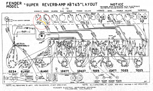
- See the wiring diagram below.
- You’ll have to solder the yellow wire to one side of the mid positioned switch in stead of to the right pot lug as before.
- Then solder a new (red) wire between the other side of switch to the right lug.
If you’re permanently disconnecting the tremolo circuit you can just clip of the brown and yellow wires and insulate the ends with tape. Note that the figure below shows the Super Reverb. The Vibrolux Reverb would be the same.
(One may also use the tremolo pedal, instead of the spst switch/pot, to entirely disconnect the tremolo. You will not need to replace the intensity pot with a spst, but let the yellow wire to the tremolo pot go through the tremolo pedal. In our opinion this is not a good idea since one loses the possibility to use both the spst switch and tremolo pedal. Using the pedal will now involve a significant click sound and volume increase.)
Blackfacing
The blackface circuits AA864 or AA964 are often targets when blackfacing silverface VRs. We’ll describe the changes that followed after AA964.
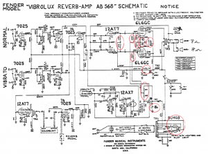
AB568 vs AA964
- The GZ34 rectifier tube was replaced with 5U4GB meaning more sag and less attack. You can select which one that matches your tone and style.
- Bias electrolytic cap was changed from 25 µF/50V to 50 µF/70V in AB568. Tone not affected.
- Voltage divider resistor in filter cap circuitry was changed from 10 KOhm to 4.7 KOhm.
- 10 KOhm resistors in bias circuits were introduced, as well as 100 KOhm resistors to the 6L6 grids before the 1.5Kohm grid resistors. In AA964 there was just one common DC feed wire to the 6L6 grid resistors.
- 2000 pF caps were introduced on 6L6 grids to filter out high frequencies, resulting in a cleaner sound.
- 150 ohm cathode resistors were introduced for robustness and safety and a 5/25V cathode capacitor was introduced to clean up distortion.
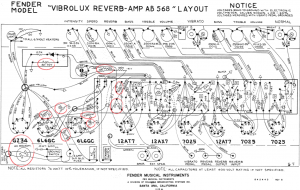
The red circles indicate the changes in figures below.
Logical schematics:
Layout:
Click images for full size versions.
Negative feedback loop
The negative feedback loop can easily be tweaked to alter the treble cut and distortion in your amp. The purpose of the NBF loop is to clean up the tone and cancel out the mid/higher frequencies and upper harmonics (distortion) at the entry point of the phase inverter which is placed in front of the power tubes. The NBF theory is that you take the signal from the speaker output, let it go through a resistor and mix it in at the entry point of the phase inverter. The speaker signal is out of phase (180 degrees) with the signal at the entry point of the phase inverter and will cancel out equal frequencies. If you disconnect the NBF loop you’ll notice that the volume increases and tone gets much more aggressive. More white noise too. unfortunately, which is why there is a NFB loop. You will fin the amp’s sweet spot at a lower volume knob setting without the NFB loop. Not only is there a volume shift, the amp’s clean headroom is reduced slightly. Most importantly the tone gets rougher and rawer with more mids and higher frequencies, aka presence. If you think your tone is too bright or harsh or you’re seeking a mellow and nice clean tone, you probably want to keep the NBF loop. This mod is for those who want more bite and a tone that really cuts through in the mix.
You may choose to implement the mod in several ways and in various combinations with the ground switch or a foot pedal. A foot pedal works like a boost/FAT pedal. If yo’re struggling to find a transparent boost pedal that keeps the natural Fender tone you should try this out. You will still have that beautiful Fender tone, just more and wilder.
- No negative feedback at all. Simply disconnect the feedback loop (a wire) and tape insulate it. You get the most effect of this mod by disconnecting the NFB loop entirely. You may experience that the tone gets harsh, depending on guitar, speakers and EQ settings of course. If so, read more about the cap in the next bullet point.
- Keep the feedback loop and install a .01 µF in series with the NBF resistor. This cap will prevent the lower and mid frequencies to go through the NFB loop. Depending on the cap value treble frequencies will be fed back to the phase inverter which cancels out the treble in the main path. The tone gets less harsh and you still have a noticeable effect. You should experiment with different cap values. Start with 0.01 µF.
- Increase the feedback loop resistance value. A good starting point is twice the original resistor value. This reduces the effect of the feedback loop, making the amp break up more when the NFB is engaged. If you make the NBF switchable there will be less volume difference if you use a high resistor value. (Using a .01 µF cap is also recommended to minimize the difference a little bit between NBF on and off).
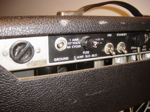
- Use the ground switch or foot pedal to make the NBF switchable. If you remove the death cap and free up the ground switch by removing existing wires to it (if you’re wondering what the ground switch does, you don’t need it). Then wire the ground switch in series with the NBF resistor. If you’re using a cap in the NBF loop this goes across the switch allowing treble to bypass independent of the switch. When the ground switch has disconnected the NBF loop the higher frequencies are still fed back through the cap. In practice you solder each the two cap legs to at each side of the switch between speaker terminal and NFB resistor.
Where to install foot-pedal or switch? The ground switch is easy available if you disable the power supply wires and death cap. For amps with reverb you could use the reverb footswitch phono plug if you are not using it.
Logical schematics
Layout
Click images for full size versions.
Mulitiple and flexible speaker output impedances (built-in attenuator)
This mod requires the knowledge of how to replace a transformer in your amp. The mod will give you mulitiple and flexible speaker output impedances where the external speaker output jack serves as a secondary independently speaker output. This flexibility is desirable for both 1×12″ or 2×10″ speaker configurations together with extension cabinets.
The original OT in the VR is sized for a 4 Ohm speaker impedance. It will make sure the power tubes “see” the correct impedance and can operate at optimal conditions in terms of clean headroom potential and frequency response. If you were to replace the original OT with a 2 ohm OT, the tubes will be pushed harder since they see a bigger load than expected (the tubes see the speakers through the OT). Both the volume and clean headroom will be reduced, yet the tone stays fairly the same (some clarity may be lost). This effect is similar to an attenuator, which is very nice when you want to achieve the amp’s sweet spot at a lower volume.
- In a 2×10″ @ 8 ohm speaker configuration, we recommend 4 ohm + 2 ohm output impedances.
- In a 1×12″ 2 8 ohm speaker configuration, we recommend 8 ohm + 2 ohm output impedances.
- Go to Mercury Magnetics web site. Order the VibroluxReverb multi-tap OT with 2, 4 and 8 ohm taps.
- Remove the original OT carefully and store it away. Install the Mercury Magnetics OT.
- Wire the OT’s primary circuit just as before. Clip the cables nicely and twist them as Leo Fender’s gently old ladies did. Insulate the unused ones with tape.
- The OT’s secondary circuit will be wired differently. Wire the 4 ohm tap to the main speaker jack. Then wire the 2 ohm tap to the ext speaker jack. You must first remove all existing wiring on the external speaker jack so that it is totally separated from the main speaker jack.
- Now you have two speaker outputs; 4 ohm + 2 ohm. You may use them independently and the ext speaker jack does not require the main speaker jack to be plugged.
We like this mod a lot. Especially since we’re using the original jack outputs. Choosing the 2 ohm output impedance with will attenuate the volume and is very useful at practise or gigs.
Middle pot
The VR did unfortunatley come without a mid pot. Many players are happy with the default 6.8K mid resistor in the EQ circuitry, but some want what the bigger amps have; a potmeter mounted in series with the 6.8 Kohm resistor (or 4KOhm for a even more scooped tone). In this way you can increase mid make your amp growl with heavy mids and a British Vox’ish tone (especially together with a Celestion speaker). We find it practically to install the middle pot at the left most side of back of the amp where the additional power supply is located. We never use this anyway and have replaced it with 10KOhm mid pots in all amps that come without one.
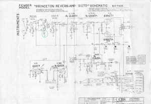
Logical schematics (Princeton Reverb, but equally for VR)
Layout
